
How a telecom rectifier system actually works
Every telecom site, from a rooftop BTS to a core switching room, runs its active equipment on −48 V DC. The rectifier system is what gets it there: it takes grid or generator AC in, and delivers regulated, battery-backed DC out, continuously, for the life of the site.
Three jobs, one cabinet
A telecom rectifier system, also called a DC power system or embedded power system, does three things at once: converts AC to 48 V DC, keeps a battery string charged and ready, and hands both to the load through a common distribution bus. If the AC fails, the load never notices, because the battery was already sitting on the same bus, not switching in after the fact.
Rectification
Rectifier modules convert three-phase or single-phase AC into regulated 48 V DC (nominal −48 V), in parallel, sharing the load.
Battery charging
The same modules float-charge the battery string and current-limit the charge so the batteries reach full state of charge without being stressed.
Distribution
A common DC bus feeds load and battery together, with breakers, fusing and surge protection sized to the site.
Hot-swap rectifier modules, not a fixed transformer
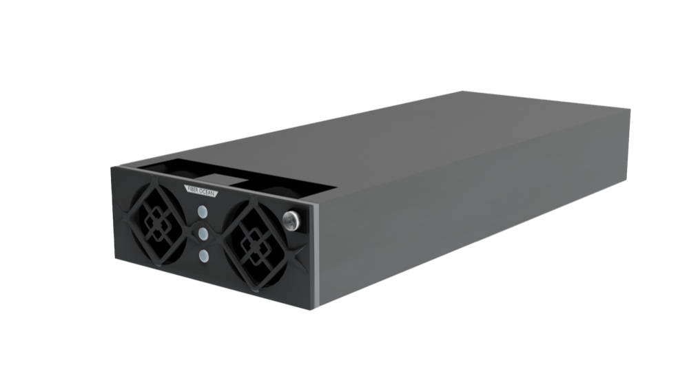
Modern systems are built from small, identical rectifier modules rather than one large fixed-output unit. FIBER OCEAN’s own RM4850 and RM4875 modules are the shared building block across the whole FO-DC platform, embedded, modular, outdoor and hybrid alike.
- RM4850: 50 A hot-swap rectifier, −48 V output, ≥96% peak efficiency.
- RM4875: 75 A hot-swap rectifier, same −48 V output and ≥96% peak efficiency, for sites needing more current per slot.
- Rated MTBF of roughly 100,000 hours per module, front-access and hot-swappable.
Because the modules are hot-swappable, a technician pulls and replaces a failed one without dropping the DC bus, and without a site visit that risks the whole system.
Three numbers decide the system size
Rectifier system sizing comes down to load current, redundancy policy and battery charge current, not the number of modules that happen to be in stock.
1. Peak load current
The continuous DC current the site draws at its busiest hour, including growth headroom for the site’s planned life.
2. Redundancy policy
N+1 is the telecom norm: enough spare module capacity that one module failure never reduces available current below the load. Higher-availability sites may specify N+2.
3. Battery recharge current
Capacity reserved to recharge the battery string within the site’s target recharge window after an outage, on top of the running load.
Add those three together, divide by the module rating (50 A or 75 A), and round up to a whole number of modules. A site drawing 120 A with an N+1 policy and a 40 A recharge budget on 50 A modules needs at least four modules for load and recharge, plus one spare, five in total, not four.
The same modules, four system formats
RM4850 and RM4875 modules are interchangeable across FIBER OCEAN’s FO-DC-48 range, so the system format is chosen for the site, not the other way around.
Related guides
Lithium batteries for telecom sites
What changes when the battery string on that same DC bus moves from VRLA to LiFePO4.
Read the guideMicro data center solutions
Where DC power fits inside a fully integrated cabinet-scale data center.
Read the guideAll Insights guides
Explainers on rectifier systems, UPS, cooling, batteries and micro data centers.
Browse InsightsFrequently asked questions
What voltage does a telecom rectifier system output?
Telecom rectifier systems output regulated 48 V DC (nominal −48 V), the standard for telecom, BTS and data center DC plant worldwide.
What is N+1 redundancy in a rectifier system?
N+1 means one spare rectifier module beyond what the load needs, so a single module failure never reduces available current below the load. FIBER OCEAN’s RM4850 and RM4875 modules are hot-swappable, so a failed module is replaced without dropping the DC bus.
How efficient are FIBER OCEAN’s rectifier modules?
The RM4850 (50 A) and RM4875 (75 A) modules both reach ≥96% peak efficiency, with a rated MTBF of roughly 100,000 hours.
Can RM4850 and RM4875 modules be mixed in the same system?
Yes. Both modules are interchangeable across the FO-DC-48 range, so a system can mix 50 A and 75 A modules to match load and redundancy needs.
How do I size a rectifier system for my site?
Add peak load current, N+1 spare capacity and battery recharge current, then divide by the module rating and round up to a whole number of modules. See the sizing section above for a worked example.
Scope your rectifier system
Share your site’s load, redundancy policy and battery plan, and our engineers will confirm the right module count and system format.