
S3 Remote Monitoring: every site, one NOC
The FIBER OCEAN S3 Remote Monitoring System pairs the S3 power and environment supervision platform with the FSU field supervision unit, proven on more than 300,000 operating sites, to bring every base station, tower and power room into one operating center.
What this system delivers
Two parts, one system: the S3 Power Supply & Environment Supervision software and the FSU (Field Supervision Unit) hardware, both feasible with different systems integration as part of an existing network.
300,000+ FSUs live
Operating today with China Mobile, China Telecom, China Unicom, China Tower and State Grid.
3,000 FSUs per server
A typical communication server accesses nearly 3,000 field units, with alarm history in the server database.
3D and map live views
Real monitoring of sites with 3D and map views, colored live by active alarm level.
Multi-vendor umbrella
Over 1,000 embedded device protocols, with TT and OAM systems integration and 24/7 customer support.
Supervision that studies your network
- Alarm intelligence · Alarm logs are saved in the server database for reports and studies of devices and alarms repeated over the last month or year.
- Live 3D and map views · Real monitoring of sites, with each site colored by its active alarm level.
- Power consumption management · Synthetical year-on-year and link-relative ratio analysis by day, month and year.
- Areas and sites model · Configure by area and site, with per-area detail and alarms.
- Open integration · Customization and integration with TT and OAM systems is feasible.
- Reports your way · Friendly, customizable reports and graphs with flexible data exporting and column display.
Six views your NOC will live in
Sites map view
Live site status on the map, every site colored by active alarm level, with an operations summary on top.
3D site view
Site structure in 3D; hover any component for its live data, with power and active alarms reported alongside.
Power consumption
Year-on-year and link-relative ratio by day, month and year; hourly data for the current day by default.
Alarm display
Active alarms stream into the list automatically as devices report them.
Alarm statistics
Historical alarms stored and reported with customized reports by area, site and date comparison.
Authority configuration
Role and rights based permissions for every user: admin, manager, user and more.
What one field unit watches
The FSU collects site data in real time and transmits it to the surveillance center NOC through site sensors and devices, and can power sensors directly from its LAN ports. IoT devices using MQTT connect too.
Power supply parameters
- AC input · Voltage and current of the 3-phase AC supply, with power rate and power factor.
- −48 VDC plant · Voltage, current and operating status of the intelligent switching power supply.
- Battery group · Charging and discharging voltage and current, single-battery voltage and surface temperature, and battery internal impedance.
- Cooling · Operating status and remote control of the intelligent air conditioner.
- Fuel · Generator tank fuel level indication.
- Protocols · Over 1,000 intelligent device protocols embedded.
Environment status and control
- Climate · Temperature and humidity monitoring.
- Safety · Smoke status, water logging status and motion detection.
- Video · IP camera media with video snapshot and storage.
- Remote control · Remote lighting control and remote entrance control.
- Sensor power · DC power for sensors through the FSU LAN ports.
- IoT ready · Connects IoT devices using the MQTT protocol.
FSU at a glance
| Item | Qty / value | Description |
|---|---|---|
| AI/DI input | 16 | 0–5 V analog or digital input; analog acquisition precision 0.5%; DI acquisition precision 100% |
| DO output | 4 | 1 A / 30 V; DO precision 100% |
| Intelligent interface (south) | 10 | 4 RS232/485 configurable serial ports, 4 RS485, 2 RS232; 1200–19200 bps |
| RJ-45 (north) | 4 | 10M/100M Ethernet, IEEE 802.3 10/100 Base-T; IP camera access |
| USB | 1 | USB 2.0 (interface for 4G module if used) |
| Total voltage of battery | 4 | Input voltage range −60 V ~ 0 V |
| Power supply for sensors | 2 | 12 VDC ±10%, current > 1 A; power > 15 W |
| Flash storage | 32 GB | Historic data storage over 3 months |
| Self diagnose & restore | – | Automatic system configuration backup on operation failure |
| Power supply | −36 ~ −72 VDC | Anti-inversed |
| Dimensions & mounting | 1U, 180 mm | 19 inch 1U rack chassis |
| Operating environment | −20 ~ 60 °C | – |
Rides the transmission you already have
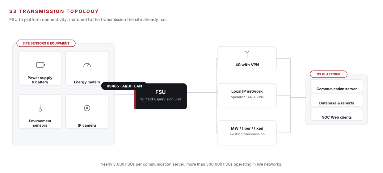
FSU to S3 connectivity is engineered around the site: 3G/4G with VPN, a local operator IP network, or existing microwave, fiber and fixed transmission.
AC-power-only sites, wired in a day
For sites with AC power only, the FSU maps the essentials straight onto its ports.
| Connection | Interface | FSU ports |
|---|---|---|
| Smart AC power meter | RS485 | A1 / B1 / GND |
| Fuel management & monitoring (high) | DI | IN1 |
| Fuel management & monitoring (low) | DI | IN3 |
| Generator failure | DI | IN5 |
| Main power alarm | DI | IN13 |
| Panel surge arrestor | DI | IN15 |
| Flash warning lights / siren | DO | DO3 |
| Aircraft warning light alarms | DI | IN2 |
| Door sensor (site fence gate) | DI | IN16 |
Where S3 keeps watch




Scope your monitoring network
Share your site count, power configuration and transmission options. Our engineers respond with a complete S3 and FSU rollout plan and quotation.